English
 عربى
عربى русский
 简体中文
简体中文


2026-07-17

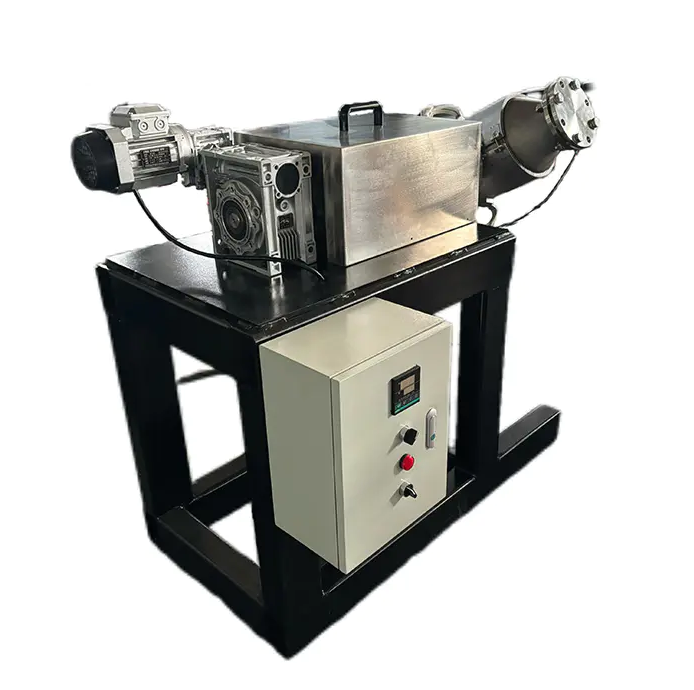
Barmag spinning machine parts are precision-engineered components designed specifically for Barmag winders, hot godets, and associated filament yarn production equipment. For textile manufacturers running continuous POY, FDY, or HOY production lines, the correct specification, timely replacement, and proper maintenance of these parts directly determines yarn quality, spindle uptime, and overall equipment efficiency (OEE). This guide covers the full range of Barmag-compatible parts, their functional roles, selection criteria, and practical maintenance standards used in professional production environments.
Barmag (now part of Oerlikon Textile) is a German-origin manufacturer of high-speed synthetic filament winders and texturing machines that dominate global chemical fiber production. The term "Barmag spinning machine parts" refers to all replaceable and wear-susceptible components used within these machines — from winder assemblies and hot godet systems to auxiliary mechanical and pneumatic parts.
These parts fall into three primary categories:
The winder is the most mechanically intensive unit in a Barmag spinning line. At winding speeds exceeding 4,000 m/min, every sub-component must maintain extremely tight tolerances to prevent yarn breakage, bobbin defects, or unplanned downtime.
The shift fork is the traverse motion component that guides yarn back and forth across the bobbin surface during winding. Barmag shift forks are available in multiple configurations — RO (Right-Out), LO (Left-Out), LU (Left-Under), and RU (Right-Under) — corresponding to the positional orientation within the winder head. Standard model series include S-1011 through S-1024, each matched to specific Barmag winder generations. Surface hardness and dimensional precision of ≤0.01 mm deviation are critical acceptance criteria for shift forks, as any wear directly causes yarn traverse irregularities.
Bearings in the winder support both the contact roll shaft and the chuck shaft under continuous high-speed rotation. Failure of a contact roll bearing is one of the most common causes of unplanned stoppages in Barmag winders. Recommended monitoring practice is to install vibration sensors with a threshold alarm at ≤4.5 mm/s, which allows early fault detection for approximately 70% of potential bearing failures before they become critical.
The lock ring secures the bobbin tube onto the chuck, while the chuck sleeve and chuck base form the mechanical interface between the spinning tube and the winder spindle. Improper fit of these components results in bobbin slippage, uneven package density, or chuck damage. Both conical and standard lock ring variants exist, and the correct type must be matched to the specific Barmag winder model.
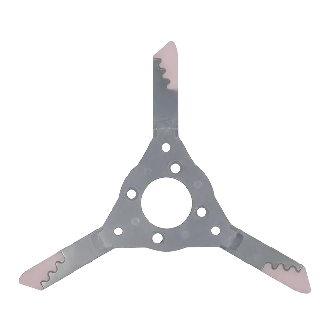
These three components form the yarn pathway within the winder. The Y-shaped fork splits the yarn path at the entry point, while the yarn guide rod and yarn guide plate control yarn tension and positioning throughout the traverse stroke. Worn or misaligned guide components are a leading cause of yarn tension fluctuations, which directly translate into denier variation in the finished package.
The tensioning block applies controlled resistance to the yarn as it enters the winding zone. Consistent tension is critical for achieving uniform package hardness and correct bobbin geometry. Tensioning blocks are classified as Class B wear parts (medium-frequency replacement), and a safety inventory of at least 5 units per production line is recommended to prevent extended downtime during changeovers.
The shift fork gear box is the mechanical drive unit that translates motor rotation into the oscillating traverse motion of the shift fork. It is a high-value component with a long lead time, and should be maintained with a safety stock of ≥2 units. The aluminum tube serves as the bobbin core tube, and its dimensional accuracy (inner diameter, concentricity) directly affects chuck fit and package formation quality.
Hot godets (also called heated rollers or draw rollers) are responsible for applying controlled heat and tension to orient the molecular structure of the filament yarn during the FDY draw-false-twist process. The key replaceable component within a Barmag hot godet is the bearing, which operates under simultaneous thermal and mechanical stress.
Maintenance standards for hot godet bearings and associated thermal components include:
Temperature calibration of Barmag hot godets should be performed using Barmag-certified calibration equipment to ensure traceability of thermal performance data.
Beyond winder and hot godet assemblies, several auxiliary parts are essential to the continuous and reliable operation of a Barmag spinning line.
Interlacing nozzles use compressed air to entangle individual filaments within a multifilament yarn bundle, creating cohesion points (interlace nodes) that replace traditional twisting. The nozzle geometry — hole diameter, air channel angle, and chamber volume — determines the interlace frequency (nodes per meter). For standard POY/FDY applications, target interlace levels typically range from 30 to 120 nodes/meter depending on yarn count and end use. Worn or partially blocked nozzles cause inconsistent interlacing, leading to downstream processing defects.
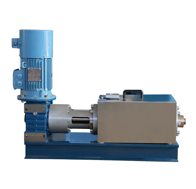
Couplings connect motor output shafts to driven machine components. In Barmag machines, flexible couplings absorb minor misalignment and vibration between drive motor and godet or winder shaft. Rigid couplings are used where precise torque transmission without angular deflection is required. Coupling inspection should be part of every quarterly maintenance cycle.
The finish guide assembly plate holds the spin finish applicator guides in position, ensuring consistent finish oil application to the yarn filaments immediately after exiting the spinneret. Uniform finish application is critical for downstream drawing and texturing performance — variation of more than ±0.1% in finish-on-yarn (FOY) level can significantly affect drawing tension and godet adhesion.
O-rings provide pneumatic and hydraulic sealing across various points in the machine — including the spin pack, interlacing block, and pneumatic yarn threading systems. Rods serve structural and positional functions within the yarn path and machine frame. Both are high-turnover consumable parts and should be maintained in sufficient stock quantities to enable rapid replacement without halting production.
Effective spare parts management for Barmag spinning machines requires classifying components by criticality and lead time. The ABC inventory classification method is the industry-standard approach:
| Class | Typical Parts | Characteristics | Recommended Safety Stock |
|---|---|---|---|
| A | Shift fork gear box, hot godet bearing, metering pump gear | High value, long delivery lead time, critical impact on uptime | ≥ 2 units per model |
| B | Tensioning block, yarn guide rod, shift fork, O-rings | Medium value, medium wear rate, moderate lead time | ≥ 5 units per model |
| C | Bolts, gaskets, aluminum tubes, standard fasteners | Low value, short lead time, widely available | Purchase on demand |
Maintaining adequate Class A inventory is especially important for global operations, where international shipping lead times for specialized Barmag components can range from 2 to 8 weeks.
A practical question for every plant manager is whether to source original Barmag OEM parts or certified compatible alternatives. The decision should be guided by the component's role in yarn quality and machine reliability:
Manufacturers with advanced CNC machining capability, Schenck dynamic balancing equipment, and plasma coating facilities are capable of producing high-fidelity Barmag-compatible parts that meet the required tolerance and surface finish standards. Verification should include dimensional inspection reports and, for rotating components, dynamic balance certification.
A structured preventive maintenance (PM) program is the most effective way to reduce unplanned downtime and extend the service life of Barmag parts. The following schedule summarizes best-practice maintenance intervals:
| Frequency | Component | Task & Standard |
|---|---|---|
| Daily | Hot godet thermocouple | Verify accuracy; acceptable error ≤±1°C |
| Weekly | Metering pump outlet pressure | Digital gauge check (accuracy ±0.1 bar); replace gear/seal if deviation >5% |
| Monthly | Metering pump & godet bearings | Inject high-temp grease (dropping point ≥300°C); fill to 1/3 cavity volume |
| Quarterly | Hot godet alignment | Laser alignment; parallelism deviation ≤0.05 mm |
| As needed | Spinneret plate | Ultrasonic cleaning (40 kHz, 60°C); aperture deviation ≤0.01 mm, Ra ≤0.4 μm |
| Annual | Full machine overhaul | Entrust to certified Barmag service providers; maintain traceable maintenance records |
Plants that implement a full PM program consistently achieve OEE targets of ≥85% — compared to the industry average of approximately 72% — and reduce unplanned downtime to fewer than 8 hours per month per line.
Modern Barmag production lines increasingly integrate condition monitoring technologies that enable predictive rather than purely scheduled maintenance:
Combining vibration monitoring with structured PM reduces mean time to repair (MTTR) by enabling pre-positioning of spare parts before a fault occurs, rather than initiating emergency procurement after a breakdown.
Incorrect part specification is one of the most common causes of premature component failure in Barmag machines. When sourcing replacement parts, the following information should always be confirmed:
The following KPIs provide a quantitative framework for evaluating the effectiveness of a Barmag spinning machine parts management and maintenance program:
| KPI | Industry Average | Best-Practice Target |
|---|---|---|
| Overall Equipment Efficiency (OEE) | ~72% | ≥85% |
| Unplanned downtime per line | >25 hours/month | ≤8 hours/month |
| Sudden failure reduction rate | Baseline | ~70% reduction vs. reactive maintenance |
| Bearing fault early warning coverage | Reactive only | ~70% of failures detected by vibration monitoring |


")

ADDRESS: No.1298, Zhouan Road, Economic and Technological Development District, Jiaxing City, Zhejiang Province
PHONE: +86 19057031687
TEL: 86-0573-83777752
EMAIL: [email protected]