 English
 عربى
عربى русский
 简体中文
简体中文


Barmag’s shift forks, which are produced by our company for Barmag in Germany, have passed...
Home / Product / Barmag Spinning Machine Parts / Winder Parts / Shift Fork Gear Box / Shift Fork Gear Box for Barmag Winder


Control the movement of shift fork
I. Historical Development
The fundamental task of the yarn traverse mechanism in a winding head is to drive the yarn guide in precise reciprocating motion along the bobbin axis, ensuring that the yarn is laid uniformly and compactly onto the bobbin to form an acceptable package. The evolution of this mechanism is closely intertwined with the broader development history of Barmag high-speed winders.
1922–1960s(Early winder era):
At the time of Barmag's founding in 1922, synthetic fiber spinning speeds were relatively low (200–800 m/min), and winding machines universally employed grooved-drum (cam) traverse mechanisms in which a closed helical groove machined on the surface of a rotating drum guided the yarn in reciprocating motion. While mechanically simple and reliable, this approach was limited by drum mass and inertia: at higher speeds, package edge formation deteriorated and groove wear accelerated sharply.
1969: A milestone in high-speed winding — the birotor traverse fork mechanism
Barmag developed the world's first high-speed winder in 1969, which represented a decisive technological breakthrough. To accommodate the substantially higher winding speeds, Barmag developed and commercialized the birotor rotary-blade traverse mechanism, the heart of which is a precision traverse fork gearbox: two rotors rotating in opposite directions each drive a rotary blade (wing) that alternately assumes responsibility for guiding the yarn, thereby achieving high-speed reversal without mechanical inertia.
In this mechanism, two counter-rotating rotors drive the rotary blades such that the yarn is alternately guided along the edge of the main guide plate and the edge of the auxiliary guide plate; after guiding the yarn in one direction, one blade descends below the guide plate while the other blade takes over guidance in the reverse direction.
1980s(Precision winding introduces new gearbox requirements):
Barmag laid the foundation in the 1980s for a completely new method of depositing yarn on packages, substantially increasing productivity. This period introduced the new requirement for precision transmission ratio control: the ratio between the yarn guide reciprocation frequency and the bobbin rotational speed (the winding ratio) had to be continuously and finely adjusted to achieve active ribbon breaking, ensuring uniform package density throughout the winding cycle.
Late 1980s–2000s(The SW→CW→ACW winder progression):
As POY/FDY spinning speeds advanced from 2,500 m/min to beyond 5,000 m/min, Barmag's winder series evolved progressively through SW (Spindle Winder) → CW (Craft Winder) → ACW (Automatic Craft Winder) generations. The CW6 winder was equipped with the Bio Rotor birotor traverse mechanism; with each generation, the precision and lubrication requirements of the traverse fork gearbox advanced correspondingly.
2007–present(The SW→CW→ACW winder progression):
As Barmag SW, CW, and ACW series winding equipment has become increasingly prevalent in China, a number of local enterprises specializing in spare parts maintenance, repair, and replacement services have emerged. Among these, Jiaxing Shengbang Mechanical Equipment Co., Ltd. was one of the earliest companies in China to develop localized maintenance and repair expertise for Barmag equipment. In response to the demanding requirements of Chinese manufacturers — high-speed production and minimal downtime — the company has refined the transmission precision and synchronization mechanisms of Barmag traverse gearboxes. The traverse gearboxes it produces are distinguished by their exceptional precision and extended service life, and have earned consistent acclaim from China's leading chemical fiber enterprises, including Tongkun Group, Xinfengming Group, Hengli Group, and Shenghong Co., Ltd.
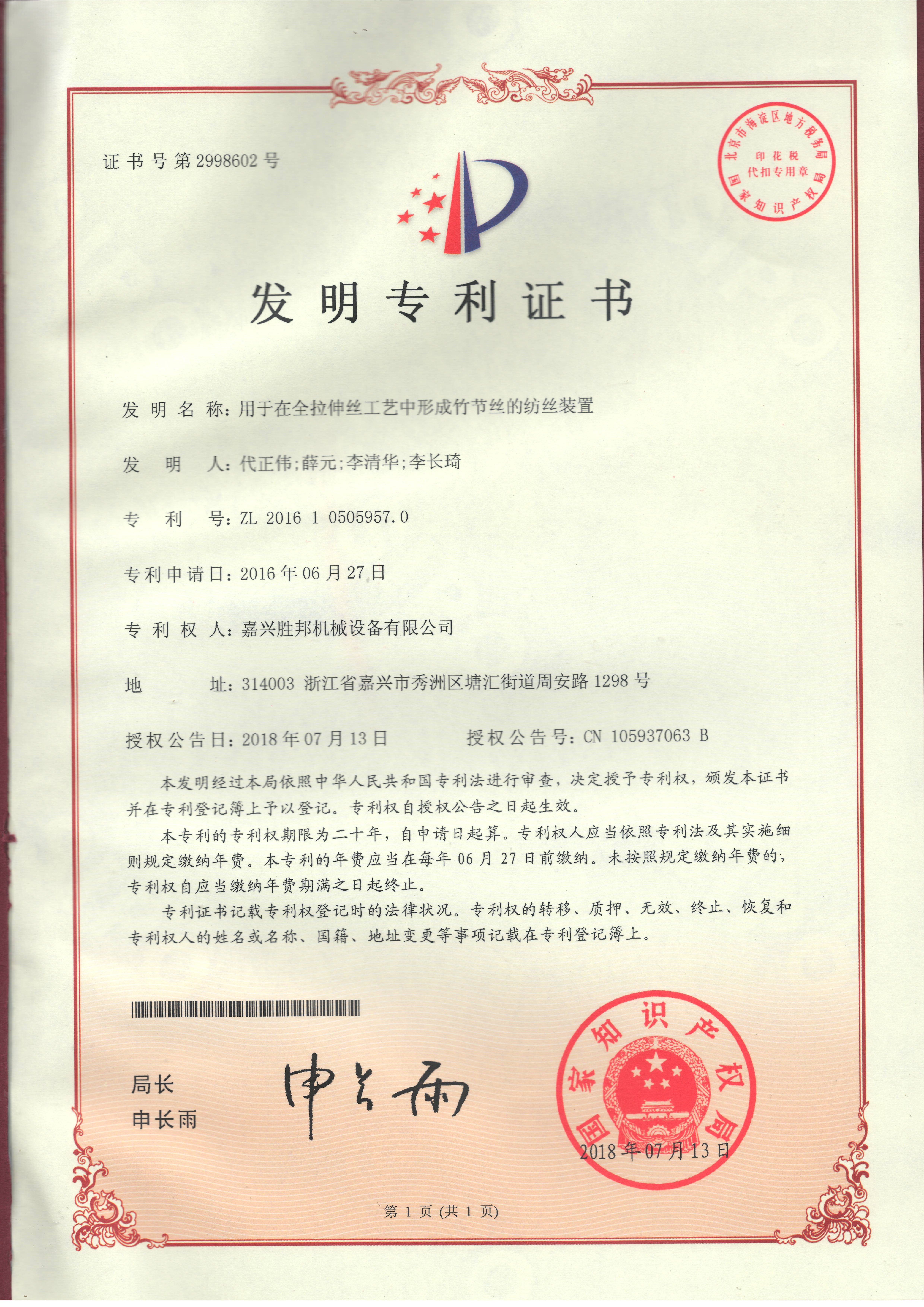
The company is equipped with an extensive array of advanced production, inspection, and maintenance facilities, including CNC machining centers, original Schenck dynamic balancing machines from Germany, plasma spraying equipment from the 625th Institute of the Ministry of Aerospace Industry, and original Barmag hot roller temperature calibrators from Germany, among others. Its independently developed bicomponent spinning test machine represents the culmination of years of accumulated expertise and advanced system integration capabilities. This machine enables the rapid production of monocomponent, bicomponent, and multicomponent fibers, as well as POY, FDY, medium-tenacity yarns, and fine-denier industrial yarns — all on a single platform. The machine has received multiple patent certifications and has been highly praised by customers in Germany, Japan, and other countries.
II. Design Characteristics and Construction
The Barmag traverse fork gearbox is a compound mechanical system integrating three core functions: precision power transmission, high-speed reversal, and accurate synchronization. Its principal constituent elements are as follows:
① Birotor rotary-blade drive assembly Two counter-rotating rotors each carry a rigidly attached rotary blade (traverse fork / wing). The two blades alternately assume yarn guidance within the traversing plane: after completing guidance in one direction, one blade descends below the guide plate while the other takes over from above, achieving continuous, uninhibited directional reversal. The winding speeds attainable with birotor rotary-blade traverse systems substantially exceed those of reversing-shaft traverse systems, making this configuration the standard choice for high-speed POY/FDY winding.
② Precision reduction and transmission gear train A high-speed motor drives the two rotors via precision helical or bevel gears. The gear transmission ratio determines the yarn guide reciprocation frequency and thereby the winding ratio. Gear precision grade requirements are ISO 5–6 (equivalent to DIN 5–6) to ensure smooth, low-noise transmission. The phase relationship between the two rotors is rigidly locked by the gear mesh geometry, guaranteeing precise timing of the handover between blades.
③ Main/auxiliary guide plate system The main guide plate (fixed) provides the guiding edges at the reversal points of the traverse stroke. The auxiliary guide plate is capable of transverse micromotion to adjust the actual reversal position, supporting the traverse stroke shift function employed in precision winding. The yarn contact edges on the guide plates are typically provided with hardened carbide or ceramic inserts to maximize wear life.
④ Y-shaped traverse fork yarn guide The Y-shaped fork (also termed push-rod fork or yarn guide fork) is manufactured from high-strength alloy or specialized composite material to ensure wear resistance and dimensional stability under high-speed operating conditions. Its principal function is to guide the yarn precisely into the winding position and, in cooperation with the traverse drive (cam or groove drum), to control yarn distribution during reciprocating motion so that the yarn is wound uniformly onto the bobbin.
⑤ Winding ratio control and ribbon-breaking system Variable-frequency drives continuously fine-tune rotor speed (i.e., traverse frequency) in real time, periodically shifting the winding ratio during precision winding to cause the yarn deposition trajectory to drift continuously, preventing repeated superposition at any single angular position (ribbon formation). The Barmag Guide control system monitors and regulates the winding ratio throughout the entire winding cycle.
⑥ Lubrication and sealing system The gearbox interior employs grease lubrication or circulating oil lubrication to protect the gear flanks at high speeds. Precision lip seals at the shaft penetrations prevent lubricant migration towards the yarn path.
III.Evolution of Associated Components
|
Period |
Principal component changes |
|
Early era (grooved drum, up to ~1969) |
Grooved drum as primary traverse element; metal yarn catchers as guides; high wear rate, frequent replacement |
|
First birotor generation (1969–1980s) |
Rotary blades introduced; metallic blades, requiring periodic replacement; guide plates in hardened steel |
|
Precision winding introduction (1980s–1990s) |
Auxiliary guide plate becomes adjustable; blades adopt wear-resistant alloy coatings; dedicated ribbon-breaking control software introduced |
|
CW/ACW series (1990–2007) |
Y-shaped fork and blades standardized across platforms; guide edges fitted with tungsten carbide (WC) inserts; gearbox housings reduced in size |
|
Practical update (2007–present) |
Refined the transmission precision and synchronization mechanisms of traverse gearboxes by companies like Jiaxing Shengbang |
Blade/fork material evolution:
Gearbox sealing material evolution:
IV. Primary Component Materials
The principal components of the traverse fork gearbox include:
V. Principal Classifications and Model Designations
Classification by traverse operating principle:
Type A — Birotor rotary-blade traverse mechanism The mainstream high-speed traverse mechanism for Barmag winders, applicable to POY/FDY/HOY processes, supporting winding speeds up to 6,500 m/min.
Type B — Reversing-shaft traverse mechanism The WinFors winder relies on the reversing shaft as its traverse system, delivering exceptionally gentle yarn treatment. Although the speeds achievable are lower than those of birotor systems, winding speeds of 2,500 to 4,000 m/min are attainable; furthermore, the winder can be converted from a 4-end to an 8-end configuration simply by exchanging the traverse system.
Type C — Groove-roll traverse mechanism Applied in industrial yarn (IDY) winding. Jiaxing Shengbang Mechanical Equipment Co., Ltd. is the only supplier in China can provide technology update services for Barmag winding system.
VI. Installation Requirement & steps
The quality of gearbox installation directly governs its operational service life. The following preconditions must be met before installation commences.
|
Inspection item |
Measuring instrument |
|
Shaft journal diameter (bearing inner race fit) |
Outside micrometer |
|
Housing bore diameter (bearing outer race fit) |
Inside micrometer/bore gauge |
|
Shaft journal cylindricity |
Outside micrometer (multi-section) |
|
Housing bore cylindricity |
Inside micrometer (multi-section) |
|
Centre distance between bearing bores |
CMM |
|
Shaft shoulder squareness |
Dial indicator with magnetic base |
All threaded connections(like Housing joint face bolts, Winding head mounting flange bolts, and Shaft locking nut) must be secured with medium-strength thread-locking compound. Flange faces must be clean and free of oil contamination.
Use a laser alignment tool to precise shaft alignment; visual estimation alone is not acceptable.
The following procedure applies to a complete gearbox swap (unit replacement). Partial component replacement (blades, seals) is addressed in the maintenance section below.
Step 1: Machine shutdown and safety lockout
Shut down the winding machine following the standard shutdown procedure; confirm that both the spindle motor and traverse motor are de-energized
Step 2: Removal of the old gearbox
Step 3: Mounting face cleaning and inspection
Step 4: New gearbox pre-installation inspection
On receipt, inspect the gearbox exterior for transport damage
Step 5: Gearbox installation
Step 6: Blade installation and phase verification
Step 7: Grease filling
Step 8: Trial run and verification
Once normal operation is confirmed, return to full production
FAQ
I. What Shengbang do in this area?
We possess a first-class engineering and technical team, combined with advanced and complete production and testing equipment, has laid a solid foundation for us to provide high-quality and first-class services to chemical fiber enterprises. Adhering to the core tenet of independent innovation, the company is committed to providing long-term, stable and comprehensive technical services for major chemical fiber enterprises, helping the industry achieve high-quality development.
II. About Shengbang's competitiveness?
Our company is equipped with advanced and comprehensive equipment for the production, inspection, testing and maintenance of chemical fiber machinery, including multi-functional CNC machine tools, original balance correction equipment from Schenck Process GmbH (Germany), plasma spraying equipment from the 625th Institute of the Ministry of Aerospace, and original godet thermal calibration instruments from Barmag AG (Germany).
Relying on years of rich experience accumulated in the field of chemical fiber production and mature system integration technology, we have successfully developed a revolutionary prototype multi-purpose spinning machine, with the help of which flexible production switching between single-component, dual-component, multi-component, Pre-oriented Yarn (POY), Fully Drawn Yarn (FDY), medium-strength yarn, ultra-fine yarn and industrial yarn can be easily achieved.
Note: This article is compiled from Oerlikon Barmag publicly available technical literature, industry journals, and patent documents. Specific part numbers for traverse fork gearboxes constitute proprietary spare-parts catalogue information; detailed specifications and current model designations should be sought directly from the Oerlikon Barmag customer service organization.
Shift Fork for Barmag")
Barmag’s shift forks, which are produced by our company for Barmag in Germany, have passed...
Shift Fork for Barmag")
Barmag’s shift forks, which are produced by our company for Barmag in Germany, have passed...
Shift Fork for Barmag")
Barmag’s shift forks, which are produced by our company for Barmag in Germany, have passed...
Shift Fork for Barmag")
Barmag’s shift forks, which are produced by our company for Barmag in Germany, have passed...
Shift Fork for Barmag")
Barmag’s shift forks, which are produced by our company for Barmag in Germany, have passed...
Shift Fork for Barmag")
Barmag’s shift forks, which are produced by our company for Barmag in Germany, have passed...

Synthetic fiber producers running BARMAG spinning, texturizing, and winding lines cannot afford unplanned stoppages. When a spindle drive fails, a hot godet lo...
View MoreColor streaking is one of the most persistent quality complaints in masterbatch-colored filament production. A spinning line can run at stable temperature and ...
View MoreA spinning production line converts polymer chips or melt into continuous filament yarn through a defined sequence of thermal, mechanical, and winding pro...
View MoreThe Barmag ACW series remains one of the most widely installed take-up winder platforms in the global synthetic fiber industry. Designed for continuous high-sp...
View MoreADDRESS: No.1298, Zhouan Road, Economic and Technological Development District, Jiaxing City, Zhejiang Province
PHONE: +86 19057031687
TEL: 86-0573-83777752
EMAIL: [email protected]
Jiaxing Shengbang Mechanical Equipment Co., Ltd. All Rights Reserved. Wholesale Shift Fork Gear Box for Barmag Winder Suppliers
